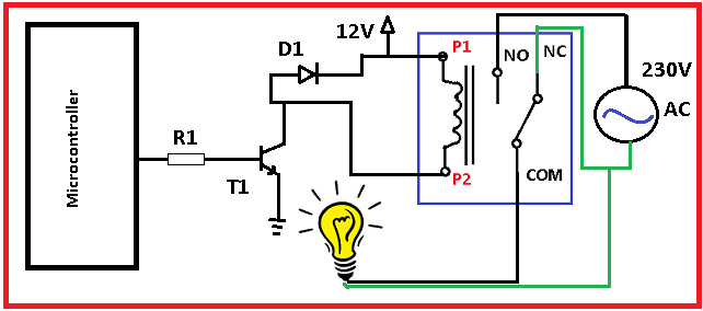

There are two types of 4 pin relays: normally open and normally closed. For example, N/O: 35A at 14VDC, N/C: 20A at 14VDC.Ī 4 pin relay controls a single circuit, whereas a 5 pin relay switches power between two circuits.Ĥ pin relays have two control pins (85 and 86) and two power switch pins (30 and 87) on a single circuit. One for normally open terminals and one for normally closed terminals. Electrical specifications for double throw relays are frequently 2 x switch. This is the switch contacts' maximum rating and should NOT be exceeded. The relay's switching circuit also has a voltage and ampere rating. The coil voltage rating specifies the voltage required for the coil to function properly. When deciding whether or not to use protection, you must consider the sensitivity of the components in the control circuit.Įlectrical ratings are provided for both the coil and the internal switching contacts in basic relays. Resistors are more permanent than diodes, but they are not as effective at removing voltage spikes. Resistors or diodes are sometimes installed across the coil of the relay for the purpose of preventing/reducing spikes from traveling back into the control circuit and damaging sensitive components. When a relay is off, the coil de-energizes, causing a great voltage spike. Relays are ideal for controlling many circuits in a car, such as headlights, electric motors, heaters, and so on. Second, relays can be placed anywhere in the vehicle to provide efficient power transfer to the electrical accessory under control. To begin with, using a relay eliminates the need for a high current rated switch or cable, which reduces cost and weight. There are several advantages to using a relay in a vehicle.


The relay diagrams shown below demonstrate how a relay works.Įxample 1: A four-pin (normally open) relay with the switch on the control circuit's positive side.Įxample 2: A four-pin (normally open) relay with the switch on the control circuit's negative side. When a relay contact is open, the power to a circuit is turned on when the coil is activated. They frequently employ an electromagnet (coil) to power their internal mechanical switching mechanism (contacts). Ⅴ What’s the difference between 4 or 5 pin Relays?Ī relay is a switch that is powered by electricity. Ⅳ How to Understand the Electrical Specifications of a Relay? When energy (electricity or charge) is supplied, the states are subject to change.ġ.1 Sample Wiring Diagrams for a Normally Open Relayģ.2 Why are Protection Devices used in a Relay? If it is closed (NC), the relay is not energized due to the closed contact. When the relay contact is open (NO), the relay is not energized. It regulates the opening and closing of an electronic circuit's circuit contacts. Relays are switches that are used to close and open circuits both electronically and mechanically.


 0 kommentar(er)
